Step into the world of electrical installations with Chapter 9 Table 8 NEC 2017, a comprehensive guide that empowers you to navigate the intricacies of conductor ampacities with ease. Delve into the depths of this crucial table, unlocking the secrets to selecting the right conductor size for any electrical project, ensuring safety and efficiency.
As you embark on this journey, you’ll discover the significance of NEC Table 8 in ensuring the proper functioning and longevity of electrical systems. Prepare to master the art of determining conductor ampacities, applying correction factors, and selecting the optimal conductor for various applications.
NEC Table 8 Overview
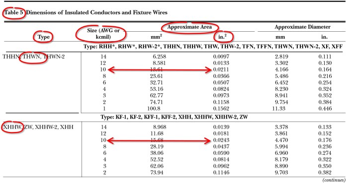
NEC Table 8 serves as a comprehensive guide for selecting conductors based on their ampacity, or current-carrying capacity, in electrical installations. It plays a critical role in ensuring the safety and efficiency of electrical systems by providing standardized values for conductor sizing under various conditions.
NEC Table 8 is essential for electrical professionals, including engineers, contractors, and inspectors, as it helps them determine the appropriate conductor size for a given application. By adhering to the guidelines Artikeld in Table 8, they can minimize the risk of electrical fires, overloads, and other hazards associated with improper conductor selection.
Significance of NEC Table 8
- Ensures the safe operation of electrical systems by preventing conductor overheating and potential electrical hazards.
- Provides standardized guidelines for conductor selection, promoting consistency and reducing errors in electrical installations.
- Facilitates efficient and cost-effective electrical designs by optimizing conductor sizing based on actual load requirements.
Column Structure and Data
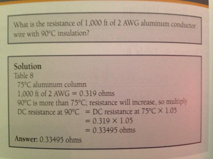
NEC Table 8 provides a comprehensive set of data for ampacity calculations. Understanding the structure and data within this table is essential for accurate electrical design and installation.
The table consists of several columns, each containing specific information:
Column: Conductor Size
This column lists the sizes of conductors in AWG or kcmil. The conductor size determines the current-carrying capacity of the conductor.
Column: Ampacity
This column provides the ampacity of the conductor in amperes. Ampacity is the maximum current that a conductor can safely carry without exceeding its temperature rating.
Chapter 9 Table 8 of NEC 2017 provides important information on electrical installations. For example, did you know that hoy es martes manana es ? Back to the topic, Chapter 9 Table 8 also covers topics such as grounding and bonding, which are essential for ensuring the safety and proper functioning of electrical systems.
Column: Correction Factors
This column includes correction factors that adjust the ampacity of the conductor based on factors such as ambient temperature, number of conductors in a raceway, and type of insulation.
Column: Example, Chapter 9 table 8 nec 2017
This column provides an example of how to use the table to calculate ampacity. For instance, if a #12 AWG THHN conductor is used in a raceway with three or more conductors, the ampacity is adjusted by a correction factor of 0.7. The corrected ampacity is then calculated as 25A x 0.7 = 17.5A.
Conductor Types and Ampacities
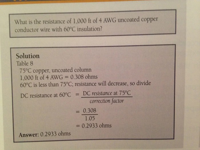
NEC Table 8 provides comprehensive information on the types of conductors and their corresponding ampacities. Understanding the various conductor types and their ampacity ratings is crucial for ensuring electrical safety and system performance.
Conductors are classified based on their material composition, insulation, and construction. NEC Table 8 covers a wide range of conductor types, including copper, aluminum, and steel.
Conductor Insulation
The insulation of a conductor plays a critical role in determining its ampacity. NEC Table 8 provides ampacity ratings for conductors with different types of insulation, including:
- Thermoplastic (THHN)
- Cross-linked polyethylene (XHHW)
- Ethylene propylene rubber (EPR)
- Polyvinyl chloride (PVC)
Determining Ampacity
The ampacity of a conductor is the maximum amount of current it can safely carry without overheating or causing damage. NEC Table 8 provides ampacity ratings for conductors of various sizes and types based on their insulation and temperature rating.
To determine the ampacity of a conductor, the following factors must be considered:
- Conductor type (copper, aluminum, etc.)
- Conductor size (AWG or kcmil)
- Conductor insulation type
- Ambient temperature
Correction Factors
NEC Table 8 provides correction factors to adjust ampacities based on various factors that affect current-carrying capacity. These factors include temperature, grouping, and ambient conditions.
To apply correction factors, multiply the ampacity value from Table 8 by the appropriate correction factor. For example, if the ampacity for a conductor is 100A at 75°C, and the conductor is installed in a conduit with four or more conductors, the ampacity must be reduced by 20%. The adjusted ampacity would be 100A x 0.8 = 80A.
Temperature Correction Factors
Temperature correction factors adjust ampacities based on the operating temperature of the conductor. As the temperature increases, the current-carrying capacity of the conductor decreases. Table 8 provides temperature correction factors for temperatures ranging from -20°C to 90°C.
Grouping Correction Factors
Grouping correction factors adjust ampacities based on the number of conductors bundled together. When conductors are bundled together, they create a “grouping effect” that reduces the current-carrying capacity of each individual conductor. Table 8 provides grouping correction factors for groups of two to nine conductors.
Ambient Temperature Correction Factors
Ambient temperature correction factors adjust ampacities based on the ambient temperature surrounding the conductors. The ambient temperature can affect the cooling of the conductors, which in turn affects their current-carrying capacity. Table 8 provides ambient temperature correction factors for ambient temperatures ranging from -20°C to 40°C.
Example Applications: Chapter 9 Table 8 Nec 2017
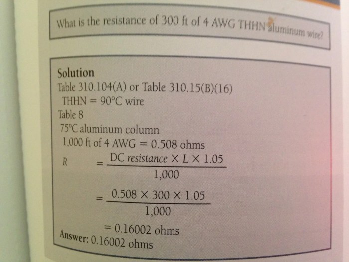
NEC Table 8 serves as a valuable tool for electrical installations, guiding the selection of conductors based on their ampacity and correction factors. Understanding how to use this table is essential for ensuring the safe and efficient operation of electrical systems.
Selecting Conductor Size and Ampacity
To select the appropriate conductor size and ampacity for a given application, follow these steps:
- Determine the load current and voltage of the circuit.
- Refer to NEC Table 8 and locate the conductor type that meets the required voltage rating.
- Select the conductor size that has an ampacity equal to or greater than the load current.
- Apply any necessary correction factors, such as temperature or derating factors, to adjust the ampacity accordingly.
Advanced Topics
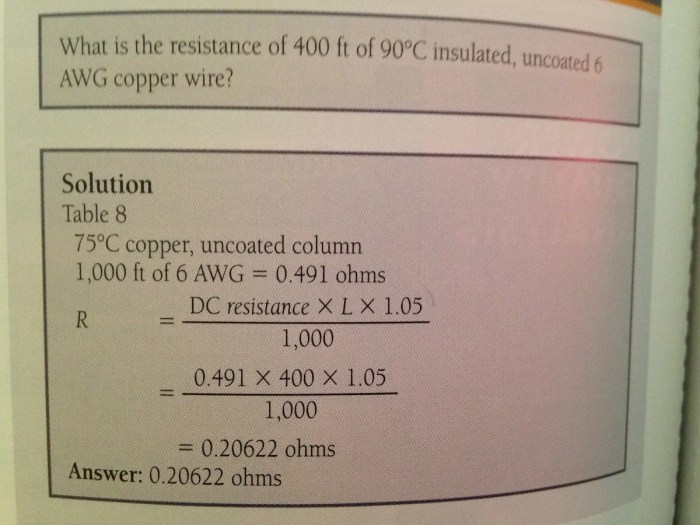
NEC Table 8 provides a comprehensive set of guidelines for conductor ampacities, but there are additional advanced topics and considerations that may arise in certain applications.
Voltage Drop Calculations
Voltage drop refers to the decrease in voltage that occurs along the length of a conductor due to its resistance. Excessive voltage drop can lead to equipment malfunctions and safety hazards. NEC Table 8 does not directly address voltage drop calculations, but it provides the necessary information to perform these calculations.
To calculate voltage drop, the following formula can be used:
Voltage Drop = (Current × Conductor Length) / Conductor Resistance
The conductor resistance can be obtained from NEC Table 8 or calculated using the conductor’s cross-sectional area and resistivity.
Non-Standard Conductors
NEC Table 8 primarily covers standard conductors, such as copper and aluminum. However, there may be situations where non-standard conductors, such as silver or gold, are used. In such cases, it is important to consult the manufacturer’s specifications for the specific conductor’s ampacity and correction factors.
Additionally, NEC Article 310.15(B)(16) allows for the use of conductors not included in NEC Table 8, provided they are listed for the intended use and installed in accordance with the manufacturer’s instructions.
Essential FAQs
What is the purpose of NEC Table 8?
NEC Table 8 provides essential data on conductor ampacities, aiding in the selection of conductors with the appropriate current-carrying capacity for electrical installations.
How do I determine the ampacity of a conductor using NEC Table 8?
Identify the conductor type, size, and insulation from the table to obtain its ampacity rating.
What are correction factors and how are they applied?
Correction factors adjust ampacities based on factors like temperature, grouping, and ambient conditions. They are multiplied by the base ampacity to obtain the adjusted value.